AReCoS

Since the 1940s, frost has stopped heat pumps from heating. Ours are designed not to.

Designed to keep the heat on without relying on backup gas or electric heat, with the optimizer built into the unit—not the cloud. Rooftop heat pumps up to 10 tons, with a ground-loop option later.

Free · no deposit · no commitment.

Controller: U.S. patent allowed, being tested with Oak Ridge National Laboratory under a research agreement (CRADA) supported by the U.S. Department of Energy · Air–water heat exchanger: patent pending · Rooftop unit: in design, chamber tests before 2027 pilots

One rooftop unit for every season A rooftop unit on a low commercial building, designed to send cool air into the building in summer and warm air in winter. Inside it, the AReCoS air–water heat exchanger, designed to keep frost to a thin, cleared layer, sits beside the embedded controller. Its water loop is a closed circuit; two connections on its side are where a ground loop can be added later, drawn as a dashed loop into the ground. Its embedded controller is designed to answer grid requests passed through the building's automation system, shown as a dashed line to the building. COOL AIR WARM AIR Embedded controller Rooftop unit Air–water heat exchanger DESIGNED TO KEEP FROST THIN Grid signal WATER LOOP Ground loop later Summer → cool air Winter → warm air

Our rooftop unit: one unit for summer and winter.

What defrost costs a conventional unit Heat delivered to a building over time. A conventional air-source unit loses output as frost builds and then stops heating briefly during each defrost, twice in the period shown. A dashed line holds near full output without the interruptions: what our air–water heat exchanger is designed to deliver. WITH OUR HEAT EXCHANGER A CONVENTIONAL UNIT 0 50 100% DEFROST DEFROST HATCHED: HEAT FROM BACKUP, NOT FROM THE HEAT PUMP time heat into the building
What defrost costs on a winter day. The heat pump stops, and gas or electric backup covers most of the gap. Ours is designed to keep heating without that down to 0 °F (−18 °C), and to hold at least 70% of its 47 °F rated heating capacity at −15 °F (−26 °C).

Refrigeration or chiller plant? Our controller is available for evaluation today

Watch

See how it works in 60 seconds.

An illustrated explainer with captions. Prototype design · Certification planned. Watch the full two-minute version.

Heat pump products

What we're building

First the rooftop unit, up to 10 tons. Then a residential size, up to 5 tons, and small chillers.

Our products

All-season heat pump RTU

Light commercial · up to 10 tons · ground-ready

Air source, with our air–water heat exchanger (patent pending) and controller inside.

Prototype design, to be updated during certification

  • 22.1IEER
  • 13.4EER
  • 3.72COP at 47 °F
  • 2.57COP at 17 °F

10-ton unit.

Designed for the bill, too. One cold morning's warm-up on backup heat can set a month's demand charge. This unit is designed to run that warm-up on the heat pump, fit a smaller circuit, and answer the grid without giving up the comfort limits you set.

Design basis

Show the design basis
  • WinterDesigned to hold 100% of its 47 °F rated heating capacity at 0 °F, and at least 70% at −15 °F.
  • Backup heatOptional electric, 10, 15 or 20 kW on the 10-ton unit, for emergency heat and loads beyond the heat pump's capacity, designed to lock out on request. Gas heat later in 2027: the heat pump leads, gas carries what it cannot, and the unit is designed to switch between them on request.
  • SummerDesigned to keep cooling up to 115 °F.
  • ControlsBACnet or a standard thermostat · manual service mode · controller designed as one replaceable board. No cloud required.
  • Grid responseDesigned to hold a kW cap, shed 15% of its power on request or 40% in a critical event, or add 15%, winter and summer, inside the comfort limits the building sets. The grid can ask; the controller decides how. How it works
  • DiagnosticsDesigned to track refrigerant charge in every mode, catch a bad sensor, and rank each fault it finds with its likely cause and when to act. On the unit and over BACnet. Catching a slow leak
More of the design basis
  • Demand modesDesigned to take these as BACnet points on the local network: setpoint or offset, kW cap, a cut or add in % or kW, shed levels, pre-heat and pre-cool, defrost request and delay, backup lock-out and, on dual-fuel units, fuel select.
  • Grid linkDesigned to take OpenADR 2.0b requests through the building automation system or a gateway, reaching the unit over wired Ethernet (IEEE 802.3), and IEEE 2030.5 and CTA-2045 through a gateway. Where there is no building system, a grid-ready thermostat wired to the unit is designed to carry the same requests. No Wi-Fi or Zigbee radio on the unit.
  • Electrical208–230 V and 460 V three-phase, 575 V optional. Designed to fit a smaller circuit: backup is not needed to cover defrost, and it is sized to the gap, none to 20 kW. 20 kW draws 55.5 A at 208 V; the full 120,000 Btu/h on resistance would draw 97.6 A.
  • ComponentsDesigned around standard compressors, valves and fans from several suppliers.
  • Ground-readyDesigned to connect to a ground loop later, without replacing the unit.
  • Water loopDesigned to be sealed and freeze-protected, with pump and fluid checks at the normal maintenance visit.
  • RefrigerantR-454B (A2L, GWP 465 by EPA’s method), with a refrigerant detection system and leak mitigation to UL 60335-2-40.
  • InteroperabilityDesigned to ship with Brick, ASHRAE 223P and Project Haystack metadata, checked with BuildingMOTIF, so building controls find each setpoint, power, demand and fault point by name.
  • Performance dataDesigned to ship in the ASHRAE 205 format across the whole operating range, from the same model the controller carries.
  • Embodied carbonA kg CO2e estimate by CIBSE TM65 North America, refrigerant included, designed to ship with the unit specification.
  • StandardsDesigned for UL 60335-2-40 listing, AHRI 340/360 ratings (AHRI 1340, IVEC and IVHE, when required) and ASHRAE 90.1. Full list

Inside the unit

Show the winter and summer diagrams
Winter, heating: the pumped water–antifreeze loop in the air–water heat exchanger is active around the outdoor coil, which is the evaporator; hot refrigerant goes to the indoor coil. Winter: heating WATER–ANTIFREEZE LOOP ACTIVE OUTDOOR AIR AIR–WATER HEAT EXCHANGER Outdoor coil (evaporator) WATER PUMP ON T AMBIENT Compressor Indoor coil (condenser) EXV P, T P, T WARM AIR TO THE BUILDING Winter, heating: the pumped water–antifreeze loop in the air–water heat exchanger is active around the outdoor coil, which is the evaporator; hot refrigerant goes to the indoor coil.Outdoor air passes the air–water heat exchanger, where the water pump drives the water–antifreeze loop around the outdoor coil. Cold refrigerant goes from the outdoor coil to the compressor, and hot refrigerant from the compressor to the indoor coil, which warms the air to the building; it returns through the EXV to the outdoor coil. Sensors read the outdoor air temperature, and the refrigerant pressure and temperature entering the compressor and leaving the indoor coil. Winter: heating WATER–ANTIFREEZE LOOP ACTIVE OUTDOOR AIR AIR–WATER HEAT EXCHANGER Outdoor coil (evaporator) WATER PUMP ON T AMBIENT Compressor Indoor coil (condenser) EXV P, T P, T WARM AIR TO THE BUILDING Summer, cooling: hot refrigerant goes to the outdoor coil, which is the condenser, and rejects its heat through the water–antifreeze loop to the outdoor air; cold refrigerant goes to the indoor coil. Summer: cooling WATER–ANTIFREEZE LOOP ACTIVE OUTDOOR AIR AIR–WATER HEAT EXCHANGER Outdoor coil (condenser) WATER PUMP ON T AMBIENT Compressor Indoor coil (evaporator) EXV P, T P, T COOL AIR TO THE BUILDING Summer, cooling: hot refrigerant goes to the outdoor coil, which is the condenser, and rejects its heat through the water–antifreeze loop to the outdoor air; cold refrigerant goes to the indoor coil.Outdoor air passes the air–water heat exchanger, where the water pump drives the water–antifreeze loop around the outdoor coil. Hot refrigerant goes from the compressor to the outdoor coil, and through the EXV to the indoor coil, which cools the air to the building; cold refrigerant returns from the indoor coil to the compressor. Sensors read the outdoor air temperature, and the refrigerant pressure and temperature leaving the compressor and entering the indoor coil. Summer: cooling WATER–ANTIFREEZE LOOP ACTIVE OUTDOOR AIR AIR–WATER HEAT EXCHANGER Outdoor coil (condenser) WATER PUMP ON T AMBIENT Compressor Indoor coil (evaporator) EXV P, T P, T COOL AIR TO THE BUILDING
  • Hot refrigerant
  • Cold refrigerant
  • Water–antifreeze loop
  • Sensor
  • AReCoS embedded controller designed to set compressor · reversing valve · EXV · fan · blower · water pump together

In every season, heat moves between the outdoor air and the refrigerant through the water–antifreeze loop: air to loop to refrigerant when heating, and back out the same way when cooling.

More: sensors, actuators and the controller All-season heat pump rooftop unit, simplified schematic A rooftop unit with an outdoor side and an indoor side. Outdoors: the air–water heat exchanger, designed to keep frost to a thin, cleared layer (patent pending), the outdoor fan, the compressor and the reversing valve. Indoors: the indoor coil and blower. Outdoor air passes through the air–water heat exchanger and leaves the outdoor section; return air from the building enters the indoor section, passes the indoor coil and leaves as supply air, so the two airstreams are separate. An expansion valve joins the two sides. Pressure and temperature sensors on the refrigerant line at each coil, and outdoor-air and supply-air temperature sensors, feed the AReCoS embedded controller, which is designed to set the compressor, reversing valve, expansion valve, outdoor fan and blower together. The water–antifreeze loop and its pump, which the same controller sets, are drawn in the winter and summer diagrams above. OUTDOOR SIDE INDOOR SIDE Air–water heat exchanger DESIGNED TO KEEP FROST THIN PATENT PENDING Outdoor fan Compressor Reversing valve EXV Indoor coil and blower P, T P, T T T AReCoS embedded controller PATENT ALLOWED REFRIGERANT SENSOR SIGNAL COMMAND All-season heat pump rooftop unit, simplified schematic A rooftop unit with an outdoor side and an indoor side, drawn one above the other. Outdoors: the air–water heat exchanger, designed to keep frost to a thin, cleared layer (patent pending), the outdoor fan, the compressor and the reversing valve. Indoors: the indoor coil and blower. Outdoor air passes through the air–water heat exchanger and leaves the outdoor section; return air from the building enters the indoor section, passes the indoor coil and leaves as supply air, so the two airstreams are separate. An expansion valve joins the two sides. Pressure and temperature sensors on the refrigerant line at each coil, and outdoor-air and supply-air temperature sensors, feed the AReCoS embedded controller, which is designed to set the compressor, reversing valve, expansion valve, outdoor fan and blower together. The water–antifreeze loop and its pump, which the same controller sets, are drawn in the winter and summer diagrams above. OUTDOOR SIDE INDOOR SIDE Air–water heat exchanger DESIGNED TO KEEP FROST THIN PATENT PENDING Outdoor fan Compressor Reversing valve EXV Indoor coil and blower P, T P, T T T AReCoS embedded controller PATENT ALLOWED REFRIGERANT SENSOR SIGNAL COMMAND

Simplified. The controller is designed to read every sensor and set every actuator together.
Residential heat pump: air source first, ground loop later An outdoor heat pump unit beside a house draws heat from the outside air, with two refrigerant lines running to the house. A dashed pipe below the unit shows a ground loop that could be added later; the unit is designed to connect to it without being replaced. Same air–water heat exchanger as the rooftop unit First: air source Later: add a ground loop
Air today, a ground loop later, in 90 seconds: an illustrated explainer with captions. Prototype design.

Residential heat pump, ground-ready

Up to 5 tons

The rooftop unit's platform in a home size.

Prototype design, to be updated during certification

  • 23.8SEER2
  • 10.9HSPF2

5-ton ducted split.

  • WinterDesigned to hold at least 70% of its 47 °F rated heating capacity at 0 °F, with optional electric backup for the coldest hours. The rooftop unit is sized for full capacity at 0 °F.
  • GridDesigned to accept utility demand-response signals (OpenADR or CTA-2045) through a connected thermostat or gateway, with capacity cap, setpoint shift and pre-heat modes.
  • DiagnosticsDesigned to track refrigerant charge in every mode, tell a bad sensor from a real fault, and name each fault's likely cause and where to look, on the unit and through a connected thermostat or gateway, so the technician arrives ready to fix it. Catching a slow leak
  • StandardsDesigned for UL 60335-2-40 listing and AHRI 210/240 ratings, with R-454B and leak detection.

Control stays in the building

No cloud in the control path. Ours only watches.

Designed to be safer than a cloud optimizer, and to do more.

A cloud optimizer sends setpoints, and start and stop commands, to your units from outside the building. If that service is breached, whoever holds it can command them. If the link drops, the optimizing stops. NIST warns that the risk of cyberattack on building controls increases significantly as they are joined to corporate networks and the cloud. AReCoS is designed to keep the optimizer, and every command, inside the units. What that means for your site.

Those commands change what each controller aims at and when it runs, not how it runs. Ours is designed to set the compressor, valves, fans and pumps together, on the machine, for the least total power. Keeping commands off the internet also addresses the EU Cyber Resilience Act’s requirement to limit attack surfaces, and our controllers and rooftop heat pump are designed to meet the Act’s essential cybersecurity requirements. Security and the Act.

With a cloud optimizer

  • Setpoints changed from the internet
  • Units started and stopped remotely
  • One more way in for an attacker
  • No optimizing when the link drops
  • Moves setpoints, not how units run

With AReCoS

  • Every command designed to stay in the units
  • Cloud optional, and it only monitors
  • Monitoring can stay offline at the store
  • Designed to keep optimizing with the internet down
  • Designed to set every actuator together

Sources: NIST, Tips & Tactics for Building Automation & Control System Cybersecurity, August 2026. CISA, FBI, EPA and DOE, Primary Mitigations to Reduce Cyber Threats to Operational Technology, May 2025: the first of its five steps is to remove control systems’ connections to the public internet.

How we make money

The optimizer is designed in. We intend to share in the savings.

A store or an office runs five or ten rooftop units, each on its own thermostat. Coordinating them usually means a supervisor in the equipment room and a subscription every year. AReCoS is designed to put that optimization inside each unit, and to let the units agree between themselves. For selected customers, we intend to be paid a share of independently verified energy savings.

Today, optimization can require

  • A supervisor in the equipment room
  • Add-on sensors and a gateway
  • Installation and integration
  • A subscription every year

With AReCoS

  • An optimizer inside every unit
  • Units designed to agree over BACnet, with no optimizer above them
  • Optional performance-based savings agreement
  • Cloud optional, for monitoring only: it never commands
  1. Unit salesAll-season heat pump rooftop units, up to 10 tons.
  2. Share of savingsFor selected customers, a share of the energy their units save, verified against a measured baseline using IPMVP methods.
  3. Controller licensingPer-unit license and integration fees from manufacturers of chillers and refrigeration systems.

Savings-share terms will be set with our pilot sites. Utilities: ask about pilots.

What is different

One controller, designed to optimize the whole unit and set every actuator at once.

It is designed to run a physics model of the whole refrigerant cycle on the unit itself. No cloud.

Patent pending

Hardware

Air–water heat exchanger, designed to keep frost thin while it heats

More about the air–water heat exchanger

A new electromechanical system is designed to limit frost to a thin, controlled layer and clear it continuously. The water–antifreeze loop is sealed inside the unit and freeze-protected, including after a ground loop is connected. Details under NDA: request the technical brief. U.S. provisional application on file. The allowed application, 18/592,624, is on the controller, not this heat exchanger.

Patent allowed

Controller

Embedded controller, designed to set every actuator together

U.S. application 18/592,624, allowed July 2026. Its hardware test is published in US 2024/0295337 A1 (FIGS. 4–7).

More on how the controller works

Equipment controls often give each actuator its own loop, and those loops interact. In the architecture of U.S. application 18/592,624, the controller is designed to estimate the states its sensors can't measure and to set the actuators together in real time. A second model is designed to screen its commands for likely component failures. The building still sets the goals, such as setpoints and schedules.

  • Startup and shutdown — designed to bring the unit up without liquid floodback, and to track where the refrigerant settles as it stops, so the next start begins from a known state.
  • Changeover — designed to sequence the compressor, reversing valve and expansion valve through each switch between heating and cooling.
  • Winter — designed to need no reverse-cycle defrost in normal operation; if the frost-clearing system faults, the unit is designed to fall back to standard defrost and report it.
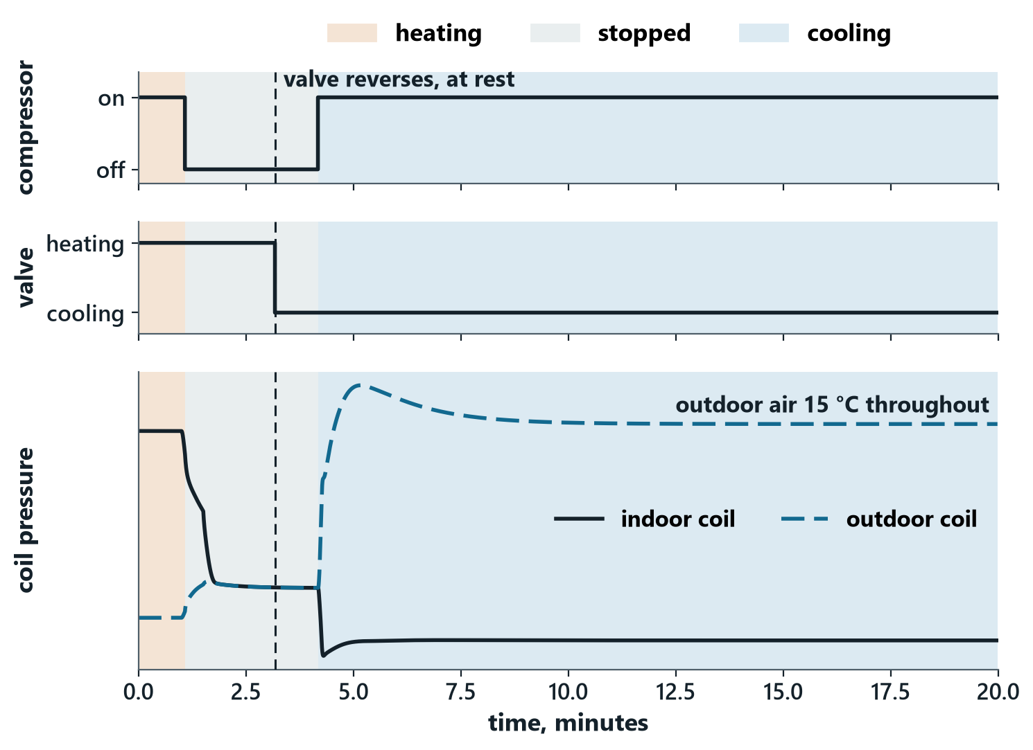
Three stacked time plots from the AReCoS heat pump model. Top: the compressor stops and, minutes later, restarts. Middle: the reversing valve moves from heating to cooling while the unit is stopped. Bottom: the indoor and outdoor coil pressures come together while it is at rest, then separate the other way round when it restarts in cooling.
One changeover on a 59 °F (15 °C) day, from the AReCoS heat pump model: the unit heats, stops, moves its reversing valve while it is at rest and the coil pressures have come together, then restarts in cooling. Amber: heating. Gray: stopped. Blue: cooling. Read it in full.
  • Optimizes itself, and answers the grid

    Designed to set the compressor, valves, fans and pump together for the lowest total power, around the clock, and to answer a grid request the same way. The grid can ask; the controller decides how.

  • Units work together

    Designed to share the load over the local network or BACnet, and to pick the best operating setpoints among themselves inside the comfort limits the building sets — all with no smart supervisory system. The cloud is optional, for monitoring only.

  • Names the cause, not the symptom

    Designed to tell the technician the likely cause and where to look: a sticking valve, a failing fan, a bad sensor, or refrigerant slowly leaking out, and how fast, in every mode. Over BACnet it arrives before the truck rolls, so the likely part is on the first truck.

  • Keeps heating in winter

    Our air–water heat exchanger is designed to keep frost thin, so the unit keeps heating without leaning on backup heat.

First units

Reserve a place in the first units.

We are targeting rooftop pilot units in 2027 and commercial units in 2028, and residential pilots in early 2028, and we plan to build them with established manufacturing partners.

  • Priority for the first units. The list decides where the first units go.
  • First to hear pricing and schedules. Shared with reservation holders before anyone else.
  • Shape the first builds. Early sites help set configurations and pilot plans.
  • No cost, no obligation. No deposit and nothing to sign.
Add details (optional)

No payment, no obligation. Your details are used only to plan the first units. Privacy.

Team

Ahmed Hussein, founder and CEO of AReCoS

Ahmed Hussein, PhD

Founder and CEO. He invented the AReCoS controller, now allowed as a U.S. patent, and the air–water heat exchanger, patent pending. He spent twelve years designing controls in automotive and aerospace. His PhD is on unsteady flow and fluid–structure interaction, and he has built physics-based fluid-thermal models of electric-vehicle battery and cabin heating and cooling.

More · Google Scholar · LinkedIn

Ahmed Atallah, physics modeling lead at AReCoS

Ahmed Atallah, PhD

Physics modeling lead. He holds a PhD in control from UC San Diego and has worked with the founder since 2022, co-leading the physical models and control algorithms at AReCoS. For ten years his work has covered physics-based modeling, estimation and optimal control: high-precision numerical integrators and orbit propagators, uncertainty quantification, nonlinear model predictive control, and sensor-fusion estimation for autonomous machines. He won the Best Paper Award at the 2019 AAS/AIAA Space Flight Mechanics Meeting.

Google Scholar

Chief technology officer

Joining soon. A vice president from the automotive industry is joining us; we will announce the name. They bring 25 years of industrial leadership, 30+ global products, close to 40 patents, and a PhD in control engineering.

How it started: read our story, from a garage test bench to rooftop units.

Research: a CRADA with Oak Ridge National Laboratory, supported by the U.S. Department of Energy

Investors: info@arecos.net

Roadmap

From a controller today to heat pumps for every season.

  1. Embedded controller for chillers and refrigeration

    Available for evaluation, fitted to your system.

    Product brief

    Evaluation today

  2. All-season heat pump RTU

    Light commercial, up to 10 tons.

    See the rooftop unit

    Pilots 2027 · commercial 2028

  3. EV heat pump

    Our heat pump and controller for the cabin and battery, for vehicle programs.

    EV heat pump

    Pilots summer–fall 2027

  4. Residential heat pump

    Up to 5 tons, on the same platform, ground-ready.

    See the residential heat pump

    Pilots early 2028

Dates after today are targets.

Let's talk.

Pilot sites for our heat pump RTU, manufacturing partners for our first builds, or our controller for your system.

Email info@arecos.net
625 Kenmoor Ave SE, Suite 350
Grand Rapids, Michigan 49546